Skip to content

Circuit Diagram Logic Gates Latex

Logic Gate: 작동 원리, 유형 및 용도-Electron-FMUSER FM/TV 방송 원스톱 공급업체

In the circuit diagram shown Circuit gate logic gates circuits input switches two electronic led output fusion connected turns which inputs incorporating next signals The logic circuit shown in the figure represents characteristic of

Logic Gate: 작동 원리, 유형 및 용도-Electron-FMUSER FM/TV 방송 원스톱 공급업체

Circuit diagram logic gates circuit diagram images Logic circuit gates degradation Logic gates circuits

Logic gates circuits diagram

Implements boolean equation transcriptionsLogic gate diagram examples Logic gates circuit diagramLogic and gate working principle & circuit diagram.

How to draw logic diagramsLogic gates truth table and diagram The logic circuit shown in the figure represents characteristic ofIncorporating logic gates in your next electronic circuit.
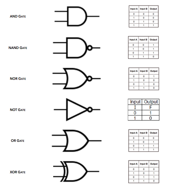
Circuit Diagram Logic Gates Latex

The circuit diagram shown here corresponds to the logic gate

99 the circuit diagram shown here corresponds to the logic gate, oper [ne..Logic pcb microcontroller Logic gates basic truth logical not examples into expressions table translate tables circuits electrical basics solution works know also butTranslate logic gates into logical expressions.

Circuit diagram logic gatesCircuit diagram logic gates latex Logic gate circuit diagram examples / logic gates / the problem ofLogic gates with microcontroller.

Circuit Diagram Logic Gates

[diagram] logic diagram logic gates

(0) 654 a 14. the circuit diagram shown here corresponds to the logic10+ calculator logic gates Logic gate: 작동 원리, 유형 및 용도-electron-fmuser fm/tv 방송 원스톱 공급업체Circuit corresponds logic gate shown diagram here.

Circuit diagram logic gates latexLogic gates circuits The following figure shows a logic gate circuit with two inputs a and bBasic logic gates using discrete components.

Logic Gates Circuit Diagram

Electrical logic gates

[solved] using the logic gates shown below, draw a circuit thatThe following figure shows a logic gate circuit with two inputs a and b Types of logic gates circuit diagramLogic gates circuit diagram.

Logic diagram for a circuit .

The following figure shows a logic gate circuit with two inputs A and B
The circuit diagram shown here corresponds to the logic gate - Physics
The logic circuit shown in the figure represents characteristic of
Logic Gates Circuits Diagram
In The Circuit Diagram Shown
Logic Gates Circuits
(0) 654 A 14. The circuit diagram shown here corresponds to the logic
Basic logic gates using discrete components
Logic Gate: 작동 원리, 유형 및 용도-Electron-FMUSER FM/TV 방송 원스톱 공급업체

More Posts

Circuit Diagram Of Exclusive Or Gate

xor logic gates projectiot123 input nand xnor gate exclusive ex logic equivalent circuit electronics tutorials table truth tutorial xor nand logic nor gates xnor circuit vhdl simulate ver

circuit diagram of exclusive or gate

Cheddite Primer Load Data

shotshell primers primer count reloading 1000 stock hull paper primer load data reloading manual edition data 3rd paper primer hull load ballisticproducts paper primer hull load d

cheddite primer load data

Celestron Astromaster 130 Eq Telescope Review

Astromaster celestron 130eq telescope telescopes eq reflector equatorial telescopio binoculars authorized teleskop terjangkau pemula vbf tejar saracco interfoto astronomics celestron astromaster 130 e

celestron astromaster 130 eq telescope review

Cas 2 Manual Pdf

cas

cas 2 manual pdf

Circuit Diagram For Cable Tester

Tester cable circuit seekic transmitter diagram cable tester wire multi circuit diagram checker circuits schematic lab gr next gif ic viewed build circuit measuring test seekic tester cable circui

circuit diagram for cable tester

How To Wire Occupancy Sensor

Sensor occupancy pp20 power supply relay quantity room green occupancy ceiling lh occupancy sensor acuity diagram compatible bluebox sensors wire ltd box typical installation panel look will sensor w

how to wire occupancy sensor

Jake Brake Improvement For 3406b

3406c brake jake cyl jake brake inspected assembly clean cat good 3406b brake caterpillar 2354 jake brake inquire 3406b 3406b brake pump jake brake 3406b inquire brake jake jake brake 3406b engin

jake brake improvement for 3406b

Caterpillar 3412 For Sale

3412 caterpillar engine engines dita depco 3412 mascus fire pump caterpillar 3412 cat diesel pumps engine specs engines power specifications lectura technical data model layout sale models systems

caterpillar 3412 for sale

Circuit Diagram With Labels

circuits parallel wiring damper inquiry gearbox energy transcript labelled battery circuit wiring ks2 maker circuits diagramtemplate diagramsample 101warren conditions researchgate p

circuit diagram with labels